Lithium-ion protection circuit module is widely embedded in lithium batteries, which is used to safeguard batteries from potential threats and risks to increase batteries’ life. So what is a protection circuit module(PCM), what are its components, and how to design and configure a PCM. The content below will offer you an answer.
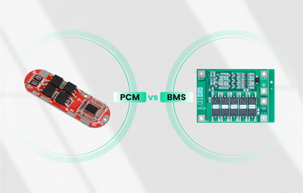
Protection Circuit Module vs BMS Module
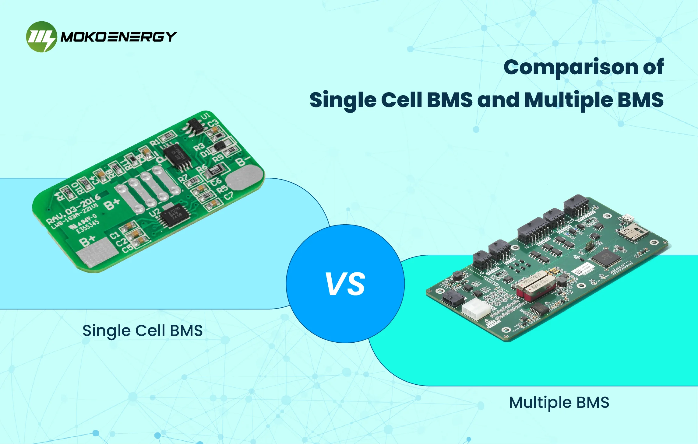
Both PCM and BMS are the most essential parts of a lithium battery, and it would be dangerous if the battery does not have them. Next is the introduction to PCM and BMS, and a contrast between them.
Protection Circuit Module(PCM)
Protection circuit module or its another name protection circuit board(PCB) is an electronic circuit mainly found in rechargeable lithium batteries. Its function is to protect and extend batteries’ life by safeguarding batteries from hazards and dangers. Apart from overcharging and disovercharging protection, it can also detect short circuit, overvoltage, temperature, and current state. In addition, it is more suitable for those applications that only need simple and basic battery protection.
BMS Module
As for the BMS module, it is an important individual component in BMS whose full name is battery management system. BMS is an electronic system used for overseeing the operations of a rechargeable battery. Multiple BMS modules and the route among those modules form a BMS, and they play the role of monitoring and managing the performance, health, and safety of batteries. As the BMS module includes single-cell module, multiple-cell module, which means that it can perform as a BMS or its subset of BMS, its function can be equivalent to BMS. Excepting those usual features of over-charging and over-discharging protection, BMS is also responsible for cell balancing, state-of-charge(SOC) estimation, state-of-health (SOH) monitoring, communication, and data logging.
Similarities Between PCM and BMS
From the above recommendation about the PCM and BMS, we can find that there are some basic similarities between them:
- Over-charging protection
- Over-discharging protection
- Short Circuit protection
- Overcurrent protection
- Overheating protection
Differences Between PCM and BMS
| Differences | Protection Circuit Module | BMS Module |
| Features | Optional balancing protection | Available features: 1. Cell balancing 2. SOC estimation 3. SOH monitoring 4. Communication interface 5. Data logging and recording |
| Structure | Stand-alone electrical circuit | A complete management system |
| Composition | More simpler with no software in it but is purely analogical. | More advanced with micro-controller and intelligent software. |
| Applications | Mainly used in 3C lithium batteries and power batteries | Mainly used in power batteries |
| Price | Low cost | More expensive |
In a word, both PCM and BMS are to protect the battery, but BMS is more sophisticated than PCM.
Protection Circuit Module Components
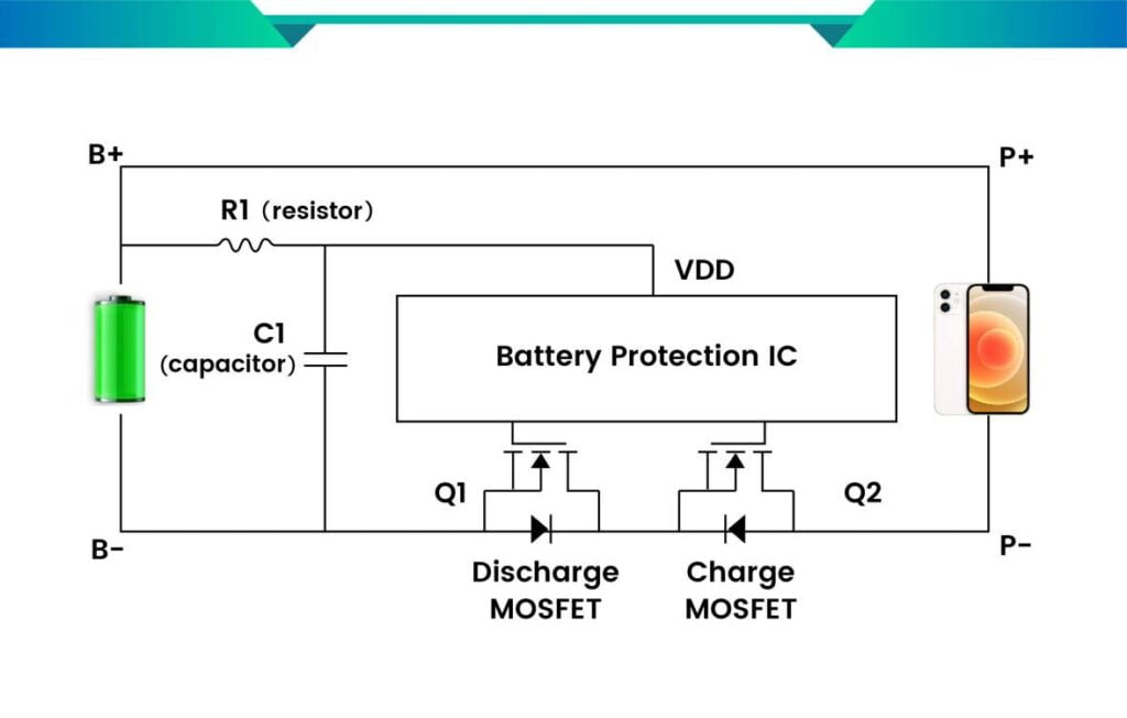
The protection circuit board would change its configurations according to different applications and the level of protection module. And it mainly includes the following four electronic components: integrated circuits(ICs), MOSFETs (Metal-Oxide-Semiconductor Field-Effect Transistors), resistors, and capacitors.
- Integrated Circuits(ICs) are used to control the switches of MOSFETs to protect batteries from over-charging and over-discharging. By measuring the voltage, IC would offer commands to MOSFETs to off the switches when the voltage is over the limit.
- MOSFETs are the control switches in batteries, one for charging and the other for discharging. It would switch off the voltage when the charging or discharging is approaching the threshold which is measured by the IC. In addition, MOSFETs should be connected in series and between the battery pack and output load.
- Resistors are the passive electrical two-terminal components whose function is to limit or adjust the current flow or lower voltage in the electrical circuit.
- Capacitors are like storage batteries that can charge and discharge. Made of two pieces of plates separated by insulated materials, it can store the charge in voltage between the positive and negative plates and discharge when needed.
Moreover, thermistors (monitor the battery cell’s temperature) and rigid or flexible printed circuit boards (PCBs) are also components of lithium-ion protection circuit modules.
Protection Circuit Module Design
We can design a protection circuit as per its usage and the threats that it probably faces. To protect against those common steady threats, such as overcharging, over-discharging, over-voltage, and over-current, passive components like capacitors, resistors, and instructors (a two-terminal component that can store the charge in current) could be used. And the active components like transient voltage suppressor(TVS) could also be installed.
For example, when it has to cope with overcharging or over-discharging problems, we can install the resistance to control the maximum charging current in the limit; the charging indicator light and the charging temperature indicator to show the charging condition and get visual feedback; the thermal interrupt to disable a cell to reduce the risk of fire; IC and MOSFETs to monitor and control current, cutting off the current when the current is over the limit.
With a feasible protection circuit module, we can improve the safety of the overall battery pack system, and provide enhanced battery performance to increase the battery’s life.
How to Configure a PCM to a Battery Pack
There are two ways to ensemble a PCM to lithium-ion: attaching a PCM to a charger or a battery pack. As the second way is always used, so next we will introduce how to configure an onboard PCM to a lithium battery pack. There are several steps we have to follow:
- Component arrangement and PCM selection: The components of PCM have many different schematic configurations that perform different functions according to power supply and the number of cells in the battery pack. For example, when selecting ICs, we should consider the thresholds of voltage and current for over-current and over-voltage. So we have to choose a suitable PCM in line with their specification and our considerations.
- Choosing battery pack: The battery pack should be attachable to the PCM, so we should select the appropriate number of cells to reach the required voltage level. If, without a suitable battery pack, we had better choose one whose limit is higher than that of PCM.
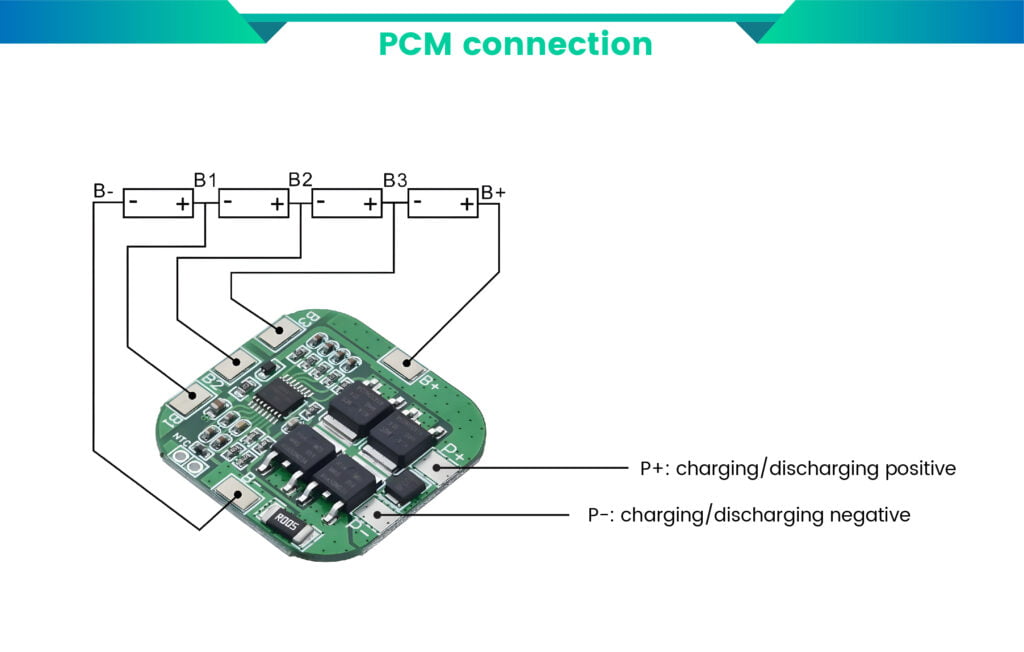
- Connection: By using appropriate wiring and connectors rated for the maximum current and voltage of the battery pack, we can connect the negative input terminal(B-) of PCM to the negative terminal of the battery pack, and link B1 to the connection between the first cell and the second cell. Repeating this operation until soldering the positive terminal of the battery pack to the positive input terminal(B+) of PCM, then the connection is over.
- Configure Protection Parameters: We can configure the parameters of PCM to customize the product as per customers’ needs. By following the instructions, we can configure it according to the specifications of the battery pack. By the way, we should also ensure that under those parameters, the battery pack would work safely and within limits.
Following the above steps, we could configure a PCM to offer lifetime protection to the battery pack.
Conclusion
From the above recommendation, I believe you will have a comprehensive understanding of lithium-ion PCM’s features and components, and how to design and configure it. Focuses on the production of both BMS and PCM, Mokoenergy possesses innovative design and guaranteed quality of products in line with the principle of “customer-first”. So please contact us if you have any needs.