A proper and functional battery management system (BMS) is crucial for ensuring the health, safety, and longevity of lithium-ion battery packs. The BMS wiring diagram acts as the central nervous system, coordinating various essential monitoring and protection circuits. However, issues in the wiring diagram (10s, 14s BMS wiring diagram, etc.) can lead to undercharged or overcharged cells, unbalanced packs, and even thermal runaway. Therefore, a properly functioning BMS wiring architecture is paramount.
In this blog post, I will provide an overview of common wiring errors and resolutions for BMS systems. Given the importance of battery packs in electric vehicles, energy storage systems, and consumer electronics, troubleshooting and fixing faults in BMS wiring is a vital skill for engineers and technicians working with lithium-ion batteries. A minor flaw in the wiring diagram can have catastrophic and expensive consequences if left unchecked. By understanding and rectifying some ubiquitous issues, we can drastically improve pack performance and extend its usable lifetime.
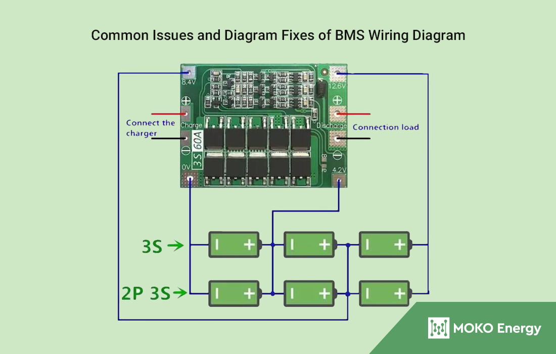
Common BMS Wiring Diagram Issues
Wiring faults and failures in a BMS can lead to serious consequences, including reduced battery performance, safety hazards, and system malfunctions. Here are some common wiring faults and failures in a Battery Management System:
Loose connections – Loose or improperly connected wires can result in intermittent connections, voltage imbalances, and inaccurate readings. This can lead to incorrect charge and discharge control, impacting the overall performance of the battery. It may even lead to problems like voltage drops, excessive heating, and even fires.
Open circuits – An open circuit occurs when there is a break in the wiring, preventing the flow of current. This can result in loss of communication between the BMS components, inaccurate measurements, and a lack of control over the battery. Wires need to be properly supported and protected from damage.
Short circuits – Short circuits in the wiring can cause excessive current flow, leading to overheating and potential damage to the BMS components and the battery itself. Short circuits can be caused by damaged insulation or incorrectly routed wires. Bare wires touching conductive surfaces can cause high current flow resulting in fires or blown fuses.
Wrong wire gauge – Using wires that are too small for the current levels can also cause overheating issues. Using the wrong wiring configuration can lead to improper communication between the BMS components, affecting the accuracy of voltage and temperature measurements. It may also result in incorrect control signals for balancing and protection functions.
Faulty sensors – Issues with current, voltage, or temperature sensors can prevent the BMS from accurately monitoring the battery. This can reduce performance or lead to unsafe conditions.
To mitigate these issues, regular inspections, proper installation practices, and adherence to manufacturer guidelines are essential.
Troubleshooting Techniques Using in Regular Inspections
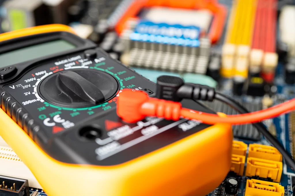
A. Using Multimeters and Diagnostic Tools
Multimeters, current clamps, wiring diagrams, and battery monitoring software are essential troubleshooting tools for BMS issues. A digital multimeter allows for checking voltages, resistances, and currents throughout a BMS system. Current clamps enable non-invasive measurement of currents in individual wires and cables. An accurate BMS wiring diagram provides a reference to trace connections and identify measurement points. Software logs help pinpoint the timing of issues.
When troubleshooting with a multimeter, first consult wiring diagrams to identify measurement points. Select an appropriate range on the multimeter matching expected values. Power off equipment and disconnect wiring for hazardous voltage checks. Probe points with multimeter leads and power on BMS to take measurements. Compare readings to nominal levels and note any deviations. Repeat checks several times to isolate intermittent problems. Refer issues outside expected ranges to wiring diagrams for further diagnosis.
B. Inspecting Wiring Diagrams
Up-to-date, accurate BMS wiring diagrams are crucial for efficient troubleshooting. They provide circuit schematics to trace connections between components, locate measurement test points, and cross-reference to hardware layouts. Clear labeling of all connectors, wires, and terminals enables systematic circuit isolation.
When inspecting wiring diagrams, use wiring diagram legends to identify color schemes and notation symbols. Follow current pathways from source, between boards and modules, to end-devices. Note key test points to facilitate physical measurements. Check diagrams against BMS hardware to ensure proper version match. Make on-paper notes and markings to incorporate diagnostic findings.
C. Visual Inspection
Visually inspect all BMS components, wiring harnesses, connectors, terminals, and solder joints for damage, wear, or contamination. Look for loose, broken, or burnt wiring/terminals. Check for moisture ingress, physical cracks, heat damage, or corrosion. Ensure connectors are fully mated with no bent pins. Identify any out-of-specification fixes or non-standard wiring. Also, you need to keep an eye out for discolored/burnt traces or terminals, arcing marks, dried electrolytic buildup, terminal burn-in marks indicating hot plugging, and stress fractures/cracks from vibration fatigue. Carefully inspect wiring insulation condition and crimp connections. Flag any damage, oxidation, moisture issues, or wiring errors for repair or replacement to prevent further degradation.
Wiring Diagram Issues Fixes
A. Overcurrent and Overvoltage Mitigation
Adjusting settings and parameters
If wiring diagrams trace overcurrent or overvoltage issues to particular BMS boards or controllers, adjust associated voltage, current and duty cycle settings to safer levels. Tune PID control loop parameters to prevent voltage/current overshoot during state changes.
Installing additional protection mechanisms
Supplement BMS with overvoltage/overcurrent protectors like fuses, breakers and transient voltage suppressors wired across vulnerable points. Select suppressor voltage thresholds and power ratings appropriate to the BMS section. Fuse currents should withstand normal load but clear overcurrent faults.
B. Balancing Batteries
Strategies for balancing batteries in the BMS
Passive battery balancing uses bypass resistors across batteries to divert excess current and equalize voltages. Active balancing uses electronics to shuttle energy between cells. Enhance wiring diagrams to include balancing wiring and upgrade BMS balancing capability if battery voltage divergence issues occur.
Implementing fixes to resolve battery imbalance
For persistent battery imbalance, replace any weak/faulty batteries with healthy matched units of equal chemistry and capacity. Exclude problematic batteries by wiring BMS monitoring and protection around them. Improve battery consistency by periodic full charge/discharge cycles.
C. Reinforcing Connections
Steps to strengthen and secure connections
Replace faulty terminals/connectors showing heat damage or corrosion. Wire stress-relieve and shield cables that may flex during operation. Prevent connectors from working loose through vibration by anchoring wiring harnesses. Apply dielectric grease on contacts to prevent moisture corrosion.
Preventive measures to avoid poor connections in the future
Enforce strict connector mating/demating procedures and use properly sized removal tools to avoid damaging pins or housings. Follow electromechanical design guidelines for wire bend radius, support spacing, and strain relief. Conformal coat circuit boards exposed to humidity/condensation risks.
Conclusion
In conclusion, adeptly troubleshooting BMS wiring is paramount for sustaining the efficiency and lifespan of battery systems. By employing techniques like multimeter usage, diagram analysis, and thorough visual inspections, users can proactively detect and rectify common issues, ensuring optimal performance and safety. Regular maintenance, coupled with effective troubleshooting, not only safeguards batteries but also contributes to the overall reliability of electrical systems.
In the realm of BMS solutions, MOKOENERGY specializes in BMS ODM and OEM services. Renowned for our commitment to quality and innovation, we collaborate with clients to deliver tailored BMS solutions that meet diverse needs. With a focus on staying at the forefront of technology, MOKOENERGY’s offerings align with the highest industry standards, making them a trusted partner in the evolving landscape of battery management. Partnering with us ensures a seamless fusion of robust troubleshooting practices and cutting-edge BMS solutions. Feel free to contact us for further cooperation.